Physics · 5 min read
How to Measure Total Intake Tract Length Including the Velocity Stack
Ls is valve to mouth — the stack is only the leftover after the runner
A velocity stack is the flared end of a longer acoustic path. This tutorial shows how to measure that path from the intake valve to the open mouth, subtract the runner you already have, and isolate the trumpet with L_stack ≈ L_eff − L_existing. The Velocity Stack Calculator reports that split; a tape on the engine is still the measurement.
Written by the My Calculator Stack editorial team. About our methods
Ls is an effective acoustic length, not a parts-catalog trumpet size. Measure along the port centerline. The split is a budget, not a dyno.
1.What you are actually measuring
The quarter-wave length is from the reflecting open end back to the intake valve (or the closest hard reflection you can defend). The trumpet on the bench is only the adjustable last section. If you measure the aluminum stack with a ruler and ignore the port, the manifold, and the throttle body, you are sizing the wrong object. On an ITB or carburetor, the existing piece is usually valve to the flange where the stack bolts on. On a manifold with a shared plenum, the reflection may not sit at the stack lip at all — this identity is weaker there.
2.Centerline, not the outside of a bend
Follow the gas path: valve head (or a published port-plus-runner length from the head shop) along the centerline of the port, through the throttle, to the plane where the stack will sit. Do not wrap a tape around the outside of a curved runner and call that Ls. A 90° cast runner can be 40–80 mm longer on the outside than on the mean line. Convert everything to millimeters before you subtract. If the head manufacturer publishes a port length, use that plus the manifold rather than guessing from a photograph.
3.The stack split
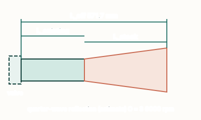
The teaching split is L_stack ≈ L_eff − L_existing − kD. L_eff is the quarter-wave target from Ls = (C × 60 × S) / (4 × N × O). L_existing is the piece you just measured. kD is an optional open-end correction (off until you turn it on). When existing length is zero, the calculator is giving you the full acoustic budget — useful while the manifold is still on paper. If the remainder is negative, the runner you already have is already longer than the tuned length: shorten it, drop to a lower order, or raise target RPM.
\[ L_{\mathrm{stack}}\approx L_{\mathrm{eff}}-L_{\mathrm{existing}}-kD \]
4.Worked example: 350 mm already there
Calculator defaults: C = 343 m/s, 6000 rpm, four-stroke, O = 3 gives L_eff = 571.7 mm. Suppose the centerline from the valve to the stack flange is 350 mm. Then L_stack ≈ 571.7 − 350 = 221.7 mm with end correction off. If you later turn correction on at D = 50 mm and k = 0.3, kD = 15 mm and the trumpet budget falls to 206.7 mm. Those 15 mm are a teaching correction, not a reason to skip measuring the 350 mm you can put a rod through.
\[ 571.7-350=221.7\,\mathrm{mm} \]
5.Type the existing length on the calculator
Enter the measured runner as existing tract length on the Velocity Stack Calculator and read the stack contribution. Leave existing at 0 only when you are still laying out the whole tract. The live figure labels L_existing, L_stack, and L_eff so the trumpet is the adjustable end, not the whole tract. Confirm the hardware on the engine; the tape and the dyno both beat a drawing.
Try it yourself
Open the related calculator and put these formulas to work.